Introduction
OPTICAL FIBRE TRENCH
An optical fibre trench (OFT) is a civil engineering work aiming at deploying optical fibre ducts or direct buried optical fibre cables. An OFT may be required for enabling a modification of the existing fibre infrastructure or to create a new or alternative path in respect to existing infrastructure (e.g. technical galleries, “caniveau”).
OFT are usually located
along roads and where future construction
activities will not overlap the
installation. Secondly, the trench should be
as direct as possible without causing
excessive damage to the roots of trees,
shrubs, or other vegetation along the route.
Depending on the method, trench width can
range from 60 cm to several meters and being
more than 100 cm deep [1].
During the
study phase, the project manager shall
specify the requirements concerning the
trench layout, the duct types, duct test
requirements, manhole specification as well
as the duct layout inside the trench and the
manhole. In addition, Project Manager shall ensure
that the installation is prepared and
executed correctly by establishing
acceptance milestones that will enable
periodical joint inspection for acceptance
of works per phase (e.g. trench digging,
ducts layout before refilling, filling up to
sand layer and green net, etc.).
 |
 |
Design criteria
WHEN IS AN OFT NEEDED?
The construction of OFTs are needed or
recommended when:
• No physical routes
(e.g. technical gallery) are existing
already between two different locations.
• The existing routes are overloaded,
preventing the correct installation of new
Optical Fibre Ducts (OFD) and cables.
•
The existing physical routes are not
suitable for blowing operation due to tight
changes of directions. The OFT built between
GT6 and GT796 is an example (see red line in
Figure 2).
Opposed to a cable tray, OFT
protects buried services with backfill
material delivering a high-level protection.
FIELD SURVEY AND WORK PREPARATION
The Project Manager shall identify all the existing underground services and formations prior to the design. At first, they need to establish the geographical position of all underground services, including deepness, by means of existing paper layout and GIS services. Further inspection on the fields are also to be done in order to validate the information coming from the existing documentation or to recuperate missing information. In particular, GPS surveys might be need to identify duct routes and manhole positions.
The services
identification request is addressed through
a “Declaration d’Intention de Commencement
de Travaux” (DICT) which shall be sent for
approval to Project Manager.
Any
trenching done near existing services should
be done very carefully to prevent accidental
damage to a service. Hand excavating might
be necessary to uncover known services prior
to commencing with mechanical excavation.
Areas where work is to be performed shall be cleared of all trees, shrubs, rubbish, and other objectionable material of any kind, which, if left in place, would interfere with the proper performance or completion of the contemplated work.
TECHNICAL SOLUTIONS
Two different solutions can be typically
adopted when placing ducts underground:
1. Place 160 mm or 200 mm pipes underground
in which will later be pulled inside 40 mm
or 50 mm OFD;
2.
Place 40 mm or 50 mm OFD directly
underground.
Solutions 1 is preferable
when a higher level of protection to the
underground services is to be delivered as
well as when the number and type of 40 mm
and 50 mm OFD is not defined yet.
Solution 2 is preferable for long OFT
(longer than 40 m) or if changes of
directions encountered prevent the bigger
pipes from being installed.
OFT ROUTE
The OFT shall be as straight as possible
in order to ease the pulling of buried ODF
or future cable installation. It is never
ideal to have directional changes, but if
unavoidable one shall keep the bending
radius as big as possible (at least 10 times
the duct/pipe diameter) and offset in the
same direction.
If a tight
change of directions (e.g. 90 degrees curve)
cannot be avoided, the installation of a
manhole (MH) shall be considered. Rigid
ducts shall then be cut at the MH
extremities and routed inside with flexible
duct.
The OFT route must be
documented on construction drawings for use
in the field. The construction drawings
should show all underground utilities and
obstacles.
Any deviation
between the planned OFT route and “as built”
OFT route should be noted on the
construction drawings and transferred to the
permanent route drawings and maps.
OFT PROFILE
It is immensely important for OFT to be
excavated to such a depth that the crown of
the OFD has at least 700 mm of backfill
cover. Where it is not possible to obtain
the specified minimum trench depth, Project
Manager
must be consulted. Concrete encasing is to
be avoided as it turns a previously flexible
duct into a long unreinforced concrete beam,
prone to fracture with ground movement.
A large concrete slab might be considered
over the crown as an additional and punctual
measure of protection if the requested depth
cannot be provided at a specific location.
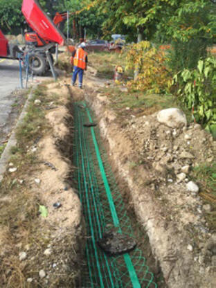
The OFT bottom is at a depth of 1 m
and layered as following:
- • A 20 cm bed of sand;
- • The Optical Fibre ducts;
- • A covering of sand, 10 cm on top of the ducts;
- • The GREEN signaling net/mesh;
- • Then back filling and finally asphalt or topcoat.
Backfill material is to be
installed in layers not exceeding 30 cm,
with each layer compacted before the next is
added.
In addition, too narrow OFT will
not allow for proper duct installation
whereas too wide OFT will result
unnecessarily costly.
The minimum
distance for a new cable/duct to pass under
other network is 0.80 m. The minimum
distance for a new cable/duct to pass next
to other network is 0.80 m.
It is obligatory to respect the
minimum distances. Other distances will be
considered where the minimum distance cannot
be respected, dependent upon CERN approval.
The Project Manager must be notified of this prior to
commencing any works.
Project Manager shall
validate the final OFT construction plan
prior to the starting of the excavation
works.
Materials
BURIED OPTICAL FIBRE DUCTS (OFD)
OFD shall be suitable for buried
installation as well as for blowing of
microducts. The diameter can range from 25
mm to 50 mm.
OFD
must be installed without any kind of
intermediate joints between manholes (MHs).
If this cannot be possible, Project Manager shall be
informed during the study phase.
The
manufacturing length of the OFD shall take
into account the required total number of
OFD and each individual total installation
distance to prevent any intermediate joint.
Any damaged duct during the installation shall be removed and replaced by a new one. In case of minor damage or if the duct cannot be replaced, an intermediate transition chamber can be installed with the prior approval of Project Manager, to allow duct access in case of microduct blockage (i.e. this can be a L3T chamber 1 m by 1 m).
It is advisable to foresee a certain number of extra OFD. This will prevent from opening the OFT in case some non-conformities are detected during the tests. The following tables list the general characteristics for 40 mm and 50 mm buried OFD:
Table 1 - General characteristics
|
Applicable standard |
NFT 54-072 |
|
Material |
HDPE, PE80 or superior |
|
Max. coefficient of friction |
0.1 |
|
Max. internal pressure |
20 bar/4 hours at 20 ˚C |
|
Colour |
Black with four longitudinal
green lines |
|
Suitable for blowing
microducts and optical fibre cables |
|
Table 2 - Dimensions of 40 mm buried ducts
|
Internal diameter [mm] |
32 |
|
External diameter [mm] |
40 |
|
Tolerance ext. diameter [mm] |
-0.0 / + 0.6 |
|
Minimum wall thickness [mm] |
3.7 |
|
Fine longitudinal grooves |
52 |
Table 3 - Dimensions of 50 mm buried ducts
|
Internal diameter [mm] |
40 |
|
External diameter [mm] |
50 |
|
Tolerance ext. diameter [mm] |
-0.0 / + 0.7 |
|
Minimum wall thickness [mm] |
4.4 |
|
Fine longitudinal grooves |
52 |
MANHOLE (MH)
MH are widely used during the creation of an OFT for two main reasons:
- ● To limit the overall distance of the OFT,
allowing intermediate (mid-point) blowing or
pulling. Indeed the MH allows splitting such
operations in several steps, decreasing the
friction of the component (i.e. pulling of
ducts or blowing of microducts).
Usually it is advisable to have access to the buried OFD at least every 0.5 km - ● To allow tight change of direction, bigger than the bending radius of the buried OFD.
Optical fibre manhole
MHs
shall be positioned as far away as possible
from road junctions in order to make easier
the excavation operations and the future
access.
Manhole are
to be sized sufficient to allow unobstructed
access for cable pulling and blowing as well
as to accommodate the bend radii of all
planned ducts.
Actual size will depend on
the number of duct entries the MH contains
and the purpose it is principally designed
for. The default manhole shall be a L5T.
In
case more than 12 OFDs are to be terminated,
a specific custom-made MH shall be designed.
MHs shall be large enough to accommodate
splice closures.
The installation of a MH deeper than 3
meters is not advisable as this will be
subject to “confined space” regulation.
OFD entry points into
MHs must be drilled, without cracking or
damaging the surrounding structure. Ideally,
any aperture shall be made in the building
fabric by core drilling or other vibration
free means.
OFD entries into MHs are to
be spaced at least 5 cm apart, both
vertically and horizontally, and at least 20
cm from the base and 25 cm from the adjacent
side walls (see below Figure).
A smaller distance can prevent coupling connectors from being correctly installed. Any aperture shall allow for a minimum of 1 cm of resin mortar to be applied around circumference of any OFD. OFD are to be cut so that a protrusion of at least 50 cm are left into the MHs. It is extremely important during the installation to ensure that distances between ducts are respected.
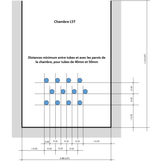
Figure 6 - OFD
entry points layout
MH shall be
equipped with a drainage system to allow
water drainage.
The MH lids shall be
complaint with safety rules and secured
against intrusion. All lids shall be equipped
with an automatic closing system with
anti-theft device.
Hinged
system are also to be installed in order to
prevent accidental damage to the underneath
services. It is advisable to install
triangle lids whenever possible in order to
reduce the overall weight of the cover.
Type and
frequency of road vehicles passing over the
lids are to be carefully considered when
choosing the robustness of the lids. Lids
installed on a road shall bear 400 kN
strength whereas others 250 kN.
Lids are
to bear a permanent identification label
defined by Project Manager.
Cablofils or
cable ladders are to be installed on the
long side of the MHs to allow optimal
positioning of ducts and cables
COUPLING CONNECTORS
Coupling connectors are to be
used inside MHs to join OFD. As for the OFD,
the connectors shall stand pressures higher
than 16 bar and be suitable for blowing
operation. It shall be compatible with all
possible materials (i.e. PE, PVC).
Datasheets of coupling connectors validated
and used at CERN are attached in [2].
Duct installation
All the works are to
be scheduled in compliance with the needs of
Project Manager.
External surface of OFD and
protected microducts shall be checked by
visual inspection prior and during the
installation. Crushed or damaged OFD shall
not be installed. OFDs crushed or damaged
during new installations shall be removed
and replaced.
It is the responsibility of
the contractor to ensure that every law
regarding traffic, safety, traffic signs and
barricading is complied with.
DUCT PULLING
When placing the OFD into an open OFT,
the bottom of the OFT must be reasonably
flat, free of horizontal and vertical bends,
and free of stones and debris. If
surrounding soil contains sharp stone or
other materials, the OFD should be insulated
with a protective layer of fine sand
(approximately 20 cm under and above the
duct). OFD extremities from drum must be
carefully inspected before pulling. No
visual damage in outer sheath shall be
accepted.
OFD shall be as straight as
possible, laid in a straight line between
MHs. In case of any directional changes, the
bending radius shall stay as big as
possible. A minimum bending radius of 10
times the outer OFD diameter is to be
maintained.
When possible, all OFD shall
be sloped properly so the will drain into
the MH and away from the building entries.
OFD can be placed into an open OFT either
directly from a drum or from temporarily
laid alongside the OFT and placed later on.
It is not recommended to hang OFD on fences,
barriers, etc.
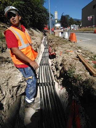
When placing multiple OFD
in a single OFT simultaneously, it is
important not to cross or twist the OFD
inside the OFT. When installing large
quantities of OFD it is possible to stack
them one on top of the other in addition to
side-by-side.
However, the OFD are to be
spaced at least 2 cm apart, both vertically
and horizontally, and attached together by
means of an OFD spacer. If ducts are to be
deployed in more than one group another,
these shall be separated apart by a 10 cm
sand layer.
The distance between is to be
checked every 10 meters in the straight
trenches and every one meter in the curved
trenches. Checks is to be made before the
trench covered by the sand or concrete
layer. The measured distances will be
reported in a data sheet.
OFD spacers
should be installed every three meters. They
prevent OFD from twisting over and around
each other. By keeping the OFD in straight
alignment, cable blowing and/or pulling
tensions will be reduced. A detectable
GREEN signaling net shall be installed in
all OFT. The tape shall be laid according to
the layout in Figure 5. Pulling ropes
shall be installed and left in every new
OFD, following OFD laying operations and
satisfactory tests.
DUCT TERMINATION
At approximately 5 meters from the MH, the
OFD formation shall open out to provide the
sufficient gap between each OFD.
OFD
shall enter and exit MHs in line with the
direction of the route, for them to be
coupled without any obvious effort, as a
continuous OFD.
Unless otherwise required
by Project Manager, the OFDs shall enter a MH at such
depths that will ensure a minimum clearance
of 60 cm below the ground surface.
All
OFD entries and exits MHs must have a
watertight seal, to prevent water, dust or
any other foreign articles from entering
into the OFD, and a proper waterproof label.
Duct integrity tests
OFD
are to be tested and proved with a
calibration and pressure test.
The tests
shall be performed after the installation of
all OFD with the OFD covered by the sand or
concrete layer.
In case of concrete
layer, it is advisable to do the calibration
tests before and after the concrete layer is
deployed. It is also advisable to verify
that all ducts have a good caudal of air at
the exit prior the starting of the tests.
The contractor shall organize, supply
the necessary test tools and execute the
checks and tests.
The contractor shall
communicate to Project Manager the dates of
the tests with at least two working days’
notice.
DUCTS CLEANING AND CALIBRATION TEST
- Each OFD installed
shall undergo a cleaning and calibration
test at the end of installation. The
OFDs shall be cleaned over their whole
length by sending a sponge of appropriate
diameter.
The uniformity of the internal surface shall be assured by conducting a calibration test of the duct. This shall be done by sending an appropriate caliber (~>=85% inner duct diameter) in the OFD under pressure. The caliber shall go across the installed ducts without interference. Any non-conformity shall be immediately reported to Project Manager. After the test, the OFD extremities shall be sealed to avoid the entrance of dust and external bodies that could jeopardize the pulling of the cables.
Here the sequence of tasks for cleaning and calibrating the OFDs.
• Foam Sponge Test - cleaning the duct:
§ A sponge is typically 100 mm in length and 2 times the OFD diameter.
§ Wet the sponge slightly with blowing lubricant.
§ Place the tight-fitting foam sponge inside the OFD.
§ At a maximum pressure of 4 bars, blow the sponge through the OFD.
§ If excess water or dirt exits the OFD, repeat the process.
§ Have a sponge catcher in place at the far end to catch the sponge when it emerges.
• Calibration Test - check for bends, kinks or blockages:
§ The sponge test MUST precede this test - a calibre can damage a dirty duct.
§ The calibre must be 80% of the duct diameter
§ At a maximum pressure of 4 bars, blow the sponge through the OFD.
§ At the receiving end, a catcher must be used. Note that a flying calibre can cause injury and/or damage!
§ Always inspect the condition of the emerged calibre, visible grooves is an indication of duct indents.
DUCTS PRESSURE TEST
Each OFD installed shall undergo a pressure
test to certify the tightness. Each OFD with
a diameter less than 50 mm shall be
pressurized with air or nitrogen at 10 bars
for a duration of one hour. Conditions can
be 2 bars for a duration of three hour in
case the OFD diameter is larger than 100 mm.
The admissible pressure drop at the end of
the test is 10% of the initial pressure. The
pressure shall be recorded every five
minutes during the entire test period.
Here the sequence of tasks for testing the
OFDs:
Pressure Test - check for coupler
leaks or OFD punctures:
§ Fit a
high-pressure end-cap to the OFD under test
on the far-side.
§ Gradually build the
pressure up to 10 bars.
§ Test all
coupling used for this test for leaks, using
soap, water and a sponge.
§ Connect the
air feed and leave this open until the
pressure in OFD stabilizes at 10 bars.
§
Close the air valve on the test assembly and
monitor the pressure gauge.
If an OFD
fails the integrity test, the duct shall be
rejected and Project Manager informed.
Documentation
The following documents
shall be provided to Project Manager at the end of the
works:
• The “as-built” construction
drawing of the OFT;
• The drawing showing
how OFDs are being terminated in the MH
(i.e. entry positions, labels);
• The
drawing showing where duct joints where
installed, if any;
• Details of any
non-conformity or suspicious signal
encountered during the installation and
test;
• The test report.
More info can be found
here